NEW - PHASE 2
NIST–ATC BLIND PREDICTION CONTEST ON DEEP,
WIDE-FLANGE STRUCTURAL STEEL BEAM-COLUMNS
CLOSED
In early 2018, National Institute of Standards and Technology (NIST) and Applied Technology Council (ATC) initiated the first phase of a Blind Prediction Contest to observe the community’s predictive capabilities of selected deep, wide-flange structural steel beam-column tests. The tests were conducted under reverse quasi-static loading at the Seismic Response Modification Device (SRMD) facility of the University of California, San Diego under the NIST-funded ATC-106-1 project.
The overarching goal of the ATC-106-1 project is to determine the fundamental behavior of steel structural members under constant or variable axial force loads for use in the future development of nonlinear modeling techniques in seismic evaluations. The first phase of the Blind Prediction Contest was concluded in April 2018 and the winners were announced during a special session of the NASCC 2018 conference.
NEW! The objective of this second phase of the Blind Prediction Contest was to quantify the impact of calibration on the modeling uncertainty. Accordingly, the force-displacement results from one specimen (Column A) was provided, and contestants were asked to submit estimated results for two other specimens (Columns B and C). Phase 2 Blind Prediction Contest was open to everyone, that is, it was not limited to Phase 1 contestants.
CONTENTS – PHASE 2 CONTEST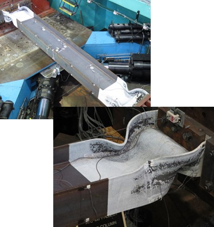
Purpose and Background
Contest Rules
Timeline
Provided Information, Assumptions, References
Submittal Rules
Questions and Answers
PURPOSE AND BACKGROUND – PHASE 2 CONTEST
NEW! In Phase 2 of the blind prediction contest, the participants were asked to predict the response parameters for Columns B and C by having access to the experimental results for Column A. The objective of Phase 2 was to assess the change in the uncertainty of predicted response of wide-flange structural steel beam-columns if, in addition to all of the data made available during Phase 1, the overall lateral load-lateral response of Column A was also made available.
CONTEST RULES – PHASE 2 CONTEST
- Contestants may consist of individuals or teams.
- NEW! If contestants participated in Phase I, please indicate so in your submittal cover letter.
- An individual can only be involved in a single team.
- If an individual is part of a team, the individual cannot not enter the competition separately as an individual.
- A company or a research institution may submit several predictions.
- Contestants will submit a single entry of one of the following three categories:
- NEW! Simple: This category is recommended for structural engineers and researchers using simple nonlinear models intending to capture the main response parameters, without the use of 3D finite element modeling software, such as Abaqus or LS-Dyna. This category will utilize the “Simple_Entry” submittal form.
- NEW! Simple-3D: This category is recommended for structural engineers and researchers using simple nonlinear models intending to capture the main response parameters. Any software may be used in this category. This category will utilize the “Simple_Entry” submittal form.
- Comprehensive: This category is recommended for structural engineers and researchers intending to model the test specimens to capture the full nonlinear cyclic response of the test specimens, and intending to predict overall and local responses. Any software may be used in this category. This category will utilize the “Comprehensive_Entry” submittal form.
- There will be one winner for each of the three categories.
- Although names and affiliations of participating teams will be recognized publicly, the results may be presented anonymously except for those of the “winning” entries.
- NEW! Questions about the blind prediction contest or details of the column specimens could be submitted via email until August 21, 2018. Questions and answers will be posted on the contest website. For updates on questions and answers, please see below.
| Event | Date |
| Submittals Due1 | September 7, 2018 |
| Category Winners Notified2 | September 22, 2018 |
1 Contestants submitted their final spreadsheet on or before 11:59pm Pacific on September 07, 2018, via email. An email acknowledging the submittal was sent to each team.
2 Category winners will be notified by September 22, 2018 via the email used for submittal.
PROVIDED INFORMATION, ASSUMPTIONS, REFERENCES – PHASE 2 CONTEST
The blind prediction contest directory contains the following information:
- Summary of contest rules
- General information on specimens and loading protocol
- NEW! Force-displacement results for Specimen A
- Material test results
- Corrected loading protocol
- Submission spreadsheets (see below for a detailed description)
- The following references that summarize previous tests conducted under this program.
- Ozkula, G., Harris, J., and Uang, C.M., 2017, Observations from Cyclic Tests on Deep, Wide-Flange Beam-Columns, Engineering Journal, 1, pp.45-59.
- Ozkula, G., Harris, J., and Uang, C.M., 2017, Classifying Cyclic Buckling Modes of Steel Wide-Flange Columns under Cyclic Loading, Structures Congress, pp. 155-167.
Computational models can assume the column ends were fastened to rigid elements as data has been post-processed to remove the flexibility occurring at the column ends due to the deformation of tie-down rods and end plates.
SUBMITTAL RULES – PHASE 2 CONTEST
Contest Now Closed
The individual or team are required to use the contest submittal spreadsheet and input values as follows:
Category A. Simple and Simple3D– Submit results using spreadsheet Simple_Entry_Phase2.xls:
- Questionnaire tab: Provide brief description of the method of analysis.
- For Specimens A and B, tested under constant axial load:
- Ratio Mmax / Mpc to two decimal places, where Mpc is the reduced plastic moment.
- Lateral force in units of kip to one (1) decimal place versus drift ratio envelope, for various drift ratios specified.
- Mode of primary nonlinear response.
- For Specimen C, tested under variable axial load:
- Ratio Mmax / Mpc to two (2) decimal places for two axial loads.
- Positive lateral force in units of kip to one (1) decimal place versus drift ratio envelope, for various drift ratios and corresponding axial loads.
- Negative lateral force in units of kip to one (1) decimal place versus drift ratio, for various drift ratios and corresponding axial loads.
- Mode of primary nonlinear response.
Category B. Comprehensive – Submit results using spreadsheet Comprehensive_Entry_Phase2.xls:
- Questionnaire tab: Describe the method of analysis
- For Specimens A and B, tested under constant axial load:
- Ratio Mmax / Mpc to two decimal places.
- Lateral force in units of kip to one (1) decimal place versus drift ratio envelope for the drift ratios specified.
- Hysteretic energy in units of kip-in to zero (0) decimal places calculated between various drift ratios.
- Column shortening in units of inches to two (2) decimal places calculated for various drift ratios.
- Mode of primary nonlinear response.
- For Specimen C, tested under variable axial load:
- Ratio Mmax / Mpc to two (2) decimal places for two axial loads.
- Positive lateral force in units of kip to one (1) decimal place versus drift ratio envelope for drift ratios and corresponding axial loads.
- Negative lateral force in units of kip to one (1) decimal place versus drift ratio for the drift ratios and corresponding axial loads.
- Hysteretic energy in units of kip-in to zero (0) decimal places calculated between the various drift ratios and corresponding axial loads.
- Column shortening in units of inches to two (2) decimal places calculated for various drift ratios and corresponding axial loads.
- Mode of primary nonlinear response.
NEW! Answers to questions regarding Phase 2 of the blind prediction contest are posted below.
Question: For specimen A, could you provide us with the axial shortening data for changing lateral drift values?
This information is not available.
Question: Was self-weight somehow countered for in the test setup of the experiment? (Like initial camber that countered self-weight deflection?).
No measures were taken to counter the self-weight deflection as it was very small.
Note the following Q&A is from Phase 1 of the contest.
Question: I´m trying to feel the comprehensive entry sheet for specimen A. I´m a bit confused with the rows indicated in the last part on the hysteretic loops. I thought these rows will correspond to those in the loading protocol excel for the drifts indicated in the table, but when I check rows 601-667 for example, I have a drift ratio of 0.036% and 0.1747%. I calculate the drift ratio as the imposed lateral displacement divided by L=18feet.
Answer: Please refer to Corrected Load Protocol r1.0, which has been uploaded in the "04 Load Protocol" folder of the blind prediction contest directory. Your question prompted a revision of this spreadsheet. During testing, data is acquired at discrete intervals. This means that the points are collected near the zero drift points but not necessarily at the zero drift. The original spreadsheet presented the data as collected, whereas the Comprehensive spreadsheet made reference to a revised spreadsheet where the zero drifts had been inserted at the corresponding locations. The revised spreadsheet includes the added zero drift rows not only for Specimen A, but also for Specimens B and C. The revised spreadsheet now includes color coded cells, and makes explicit reference to the key points in the hysteretic responses. Since the applied axial force at the zero drift points was not measured, we suggest that participants linearly interpolate the axial load using the measured drift ratio and axial load points above and below where the zero drift rows were inserted.
While reviewing the spreadsheet we found that the drift ratios listed in cells D53-E57 of worksheet “Specimen C” had been mistakenly calculated using a column length of 216 in. The correct length is 212 in. The correct drift ratios are listed in r 1.0 of the Corrected load protocol.
Question: It is not clear in the Simple Entry spreadsheet at what cycles the predictions are to be made. Please confirm that the predictions are to be made at the points indicated in the image, below. 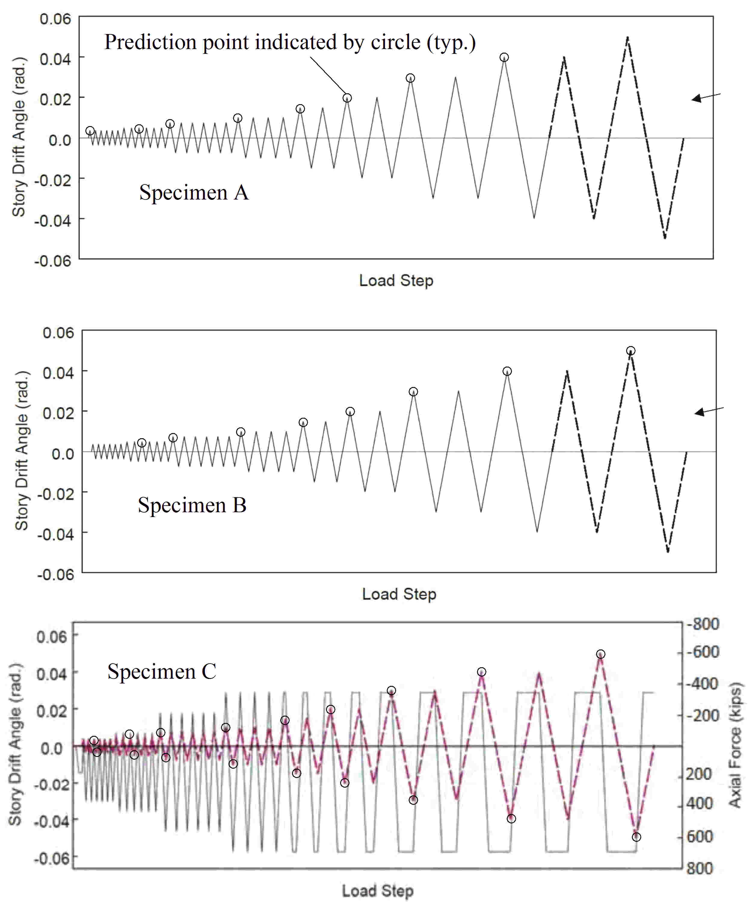
Answer: The interpretation is correct.
Question: I wonder if the measured dimensions of the specimens are available.
Answer: A file containing this information “Measured section dimensions for Specimens A-B-C.pdf” is now posted in the “02 Test Specimen Information” folder of the blind prediction contest directory.
Question: Would you please let me know the geometry of the specimens used to obtain the material properties listed in Table 2 of the reference: "2017a Ozkula et al. (Observations from Cyclic Tests on Deep Wide Flange Beam Columns)".
Answer: A file containing this information “tensile coupon dimensions for 2017a.pdf” is now posted in the “06 References” folder of the blind prediction contest directory.
Question: Regarding the units on the material test coupon C -- want to confirm that the units should be as listed in the data [in/in] and not as plotted [%], i.e. failure strains are on the order of 40%/25%, and not less than 1%.
Answer: The test data for all three specimens are correct; however, the horizontal axis for Specimen C tensile coupon test results was not labelled correctly. A corrected file, Engineering Stress-Stress Data_rev1.xls, is now posted under Material Test Results in the blind prediction contest directory.
Question: Would it be possible to provide the chemical decomposition of the specimens’ steel materials?
Answer: The chemical properties of Specimens A, B, and C are provided in the table shown below and also uploaded as a pdf under the Test Specimen Information folder in the blind prediction contest directory.
Mill Certificate: Chemical Composition
| Specimen Designation |
Column Size |
Chemical Composition (%) | |||||||||||||
| C | Si | Mn | P | S | Cu | Ni | Mo | Cr | Al | V | Nb | Sn | CE | ||
| A | W30×148 | 0.17 | 0.15 | 0.104 | 0.013 | 0.011 | 0.23 | 0.08 | 0.02 | 0.12 | 0.002 | 0.056 | 0.001 | 0.013 | 0.4 |
| B | W14×82 | 0.08 | 0.2 | 0.2 | 0.02 | 0.032 | 0.34 | 0.11 | 0.022 | 0.18 | 0.003 | 0.001 | 0.021 | 0.01 | 0.29 |
| C | W18×130 | 0.07 | 0.23 | 1.3 | 0.015 | 0.025 | 0.32 | 0.11 | 0.03 | 0.15 | - | 0.04 | 0.001 | 0.01 | 0.36 |
Question: The submittal date on the announcement email listed January 22, 2017. Has the deadline passed for submittals?
Answer: We apologize for the mistake. The submittal deadline is January 12, 2018. Good luck!
BLIND PREDICTION CONTEST PHASE 1 RESULTS
The winning team in the simple category (using simple nonlinear models intending to capture the main response parameters) includes JJ Tobolski (Project Engineer) and Zachary Treece (Senior Engineer) of Thornton Tomasetti, Chicago, Illinois. The entry utilized Abaqus software and earned the highest number of points of the 15 entries when judged against the test results.
The winning team in the comprehensive category (demonstrating the full nonlinear cyclic response of the test specimens, and intending to predict overall and local response parameters) includes Alexander Hartloper (Doctoral Assistant), Ahmed Elkady (Postdoctoral Research Scientist), and Dimitrios G. Lignos (Associate Professor) of Ecole Polytechnique Federale de Lausanne (EPFL) Switzerland. The entry utilized Abaqus software and earned the highest number of points of the 11 entries when judged against the test results.
In addition to the two winners, the contest judges would like to commend Mariyam Amir (PhD Student), K.G. Papakonstantinou (Assistant Professor), and G.P. Warn (Associate Professor) of the Department of Civil Engineering at the Pennsylvania State University. This team’s results in the comprehensive category were developed by their own code and model, developed in Matlab, and earned the second highest number of points when judged against the test results.
One representative of each of the three teams presented their methods and findings at the AISC Steel Conference (NASCC) in Baltimore, Maryland on Friday, April 13, 2018 in Session V1, Blind Prediction of Cyclic Response of Deep Wide-Flange Columns for Special Moment Frame Applications. Also in this session, Professor Chia-Ming Uang of University of California San Diego provided a summary of the overarching testing program. The session will be moderated by James O. Malley of Degenkolb Engineers, San Francisco.